3D printing best practices
GrabCAD Print makes 3D print prep simpler by allowing you to work directly with your native CAD files without having to export to STL first, and by allowing you to arrange and slice all in the same viewer, without having to go to an intermediate toolpath file.
Despite this, there are still several factors which are left to your discretion which can have a large impact on whether your print comes out satisfactory. This article will describe how to use GrabCAD Print to get the best results.
Part orientation
There are 6 things to consider when deciding the orientation your part will be built in. You should weigh all of them out before selecting an orientation because each one can have a big impact on your build. Chances are there is going to be something that will need to be sacrificed; what you decide to sacrifice will be dependent on your design intent.
Speed/build time
Part orientation can have a huge effect on the amount of time it takes to build your part. Generally the shorter your part is in the Z axis the faster it will build. The part on the left below would take much longer to build than the same part laid down on the right.

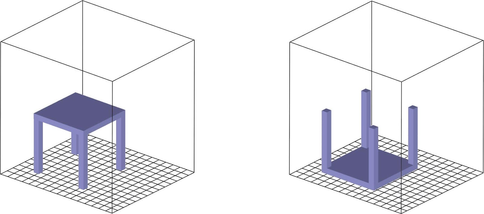
Support usage
Support usage is also dependent on part orientation. Any overhangs must be held up by support material. In the example below the stand on the left would have a very large amount of support under it whereas the stand on the right would use a very minimal amount of support. Less support material will also shorten your build times.
Surface quality
When there are curved surfaces on the top or bottom of the part they will appear “stair stepped” after being built. By orienting the part with curved surfaces positioned in the Z axis (to the sides) the surfaces will appear much smoother. In the example below the wings and fuselage of the jet on the left will have a stepped appearance, the jet on the right will take longer to build, but the finished appearance will be much better.

Support removal
Support removal is a concern especially when using breakaway supports. In the example below, the supports filling the longer hole on the left part will be difficult to remove since they are deep inside the part. The same part on the right will not need supports in the longer hole since it is vertical and the supports in the shallower holes will be relatively easy to remove.

Part strength
Part orientation has a large effect on part strength. When stress will be applied to a part such as the broom holder below it is better for the tabs to be in the same layer as the body of the part (part on the right). The adhesion of one layer to another is weaker than the adhesion of the layer within itself. The part on the left would be much weaker when used as a functional model. You can think of it like splitting wood. It is easy to split with the grain but very hard across the grain.

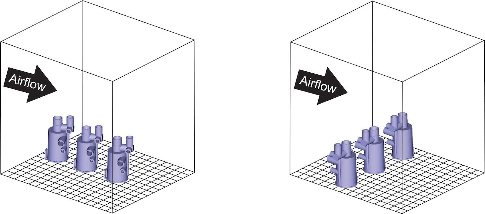
Airflow
The airflow in the build chamber helps cool each layer to envelope temperature as the system builds. It is better to align parts in the y axis (right example) to prevent airflow from being blocked to other parts (left example). It is also good to keep detailed and supported sections of the part facing the left side of the build chamber (right example). This allows areas where support and model material meet to be cooled evenly to prevent distortion in the parts.
Material properties
The specific options available for material properties, for both the selected model and whole tray, vary depending on the type of printer you are using. Below are some general guidelines.
Slice height
In general thinner layers will allow finer details but will extend build times. Thicker layers will shorten build times but increase the minimum feature size.
.010” is the “standard” layer thickness and is good for most applications. .007” and .005” are used for small parts that require fine detail. .013” is generally used on large parts where fine detail is not a requirement.
Interior fill styles
When building a part there are several interior fill styles to choose from. The style you choose will depend on the intended use of the part. If you are using a 250mc there are additional options.
Solid-normal: no open areas on the interior raster fill and one contour toolpath. This will create the strongest part and use the most material.

Sparse: a uni-directional raster interior combined with multiple contours around the part boundaries. This will use the least material and also be the least durable choice.

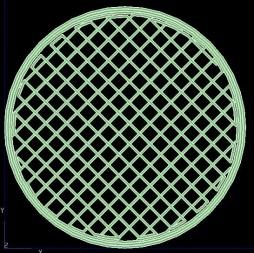
Sparse – double dense: Sparse double dense is bi-directional raster interior creating a grid pattern again with multiple contours around the boundaries. This is a good compromise between material usage and part strength.
Support style
Supports are generated to support overhangs and prevent the part from collapsing while it is being built. There are five different support types, each has a specific use.
SMART supports will narrow or widen as they get farther from the part to best support the model while reducing the amount of support material used. SMART supports are suitable for all models, especially those with large support regions, and are the default setting for printers using soluble support material.
Sparse supports have vertical sides. Sparse uses more support material than SMART but it is also more stable for tall, skinny parts.

Surround supports are used to keep tall thin parts from falling over. Surround supports completely encase the model in support.

Basic supports are typically used with breakaway support material. They have a raster pattern with no contour around them.


Self-supporting angle
Supports are generated whenever the angle of the part surface falls below a certain angle known as the self-supporting angle. The recommended value for self-supporting angle varies for different materials and slice heights. This value is conservative to provide the best opportunity for a successful print.
The self-supporting angle may be changed, resulting in less (or more) support created. This ability is provided to allow experienced designers to apply their knowledge of material behavior when printing to achieve a successful print. Whenever the self-supporting angle is changed GrabCAD Print makes it easy to return to recommended value by selecting the Default action.
Tray arrangement
In GrabCAD Print, the Arrange tool has two options for automatic arrangement: "Arrange tray" and "Arrange project." They work in the same way, except that Arrange tray will only arrange parts on the current tray, and Arrange project will arrange all parts across all of the trays. Here's how they work:
- Each part has a theoretical bounding box (cube shape) drawn around its largest dimensions
- The parts are then placed on the tray(s) starting in the home corner (varies by printer type) from largest to smallest, giving a .25" buffer around each bounding box.
- This does not adjust the orientation of any part.
Because most parts are not cube-shaped, often parts can be successfully printed much closer together than the auto arrangement will place them. Click and drag to move parts around the tray, and right click on parts to send them between trays.
How close can you place parts?
Unless a part is intersecting with another on a tray, you will be able to go into slice preview or print that tray, but it may fail while the tray is being processed. The reason for this is because the supports may be intersecting, but GrabCAD Print cannot know what the supports will look like until the tray is processed.
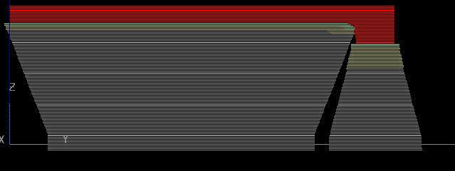
This is how close "Arrange tray" places these parts: 
Once the tray has been sliced, the first support layer will be highlighted if the parts are too close to print:
